Sunday, 9 June 2013

Making the photo interrupter mechanism and robot base, location programming continues

 The interrupter mechanism is used to sense how far each motor has moved, and in doing so record the position of the gantry crane at all times.To do this I attached a small cut out shape which will block the signal going through the photo interrupter as it spins. This was made using 3 layers of 1mm styene sheet. The first main layer was in the shape seen below. It is essentially a circle 40mm diameter, split in 4 equal segments, with two of the opposite segments cut out. This was done working around a concentric circle diameter 25mm. The drawing of this is underneath (not to scale). The other two layers were just two small circles of styrene approx. 15mm in diameter that were punched out by a hollow punching tool. These were glued together using styrene glue and a 4mm hole was drilled in the centre using a vertical milling machine to pass through the motor.
Below are some pictures of the finished x and y wheel attached (only with blu tack at the moment):

 The other major change was, a base for the robot has been added. This is just a 320 x 450 x 6 mm wooden board that was cut to size with the ban saw and then sanded down. Using the vertical milling machine again, holes were drilled either side of where each leg would go. A cable tie was then fed through the lego and holes, and secured to mount the robot to the base. The circuit board is not attached at the moment but will be soon using Hex Standoffs.
The most work has gone into the code today. After much fiddling with the code, interrupts just didn't want to work, so this has all been replaced using other alternatives. This has resulted in quite a large messy code with many variables but the main point is it functions as needed. In addition, an index has been created of commands that can be run in serial. These are:
xf=X goes forward
xs=X stops
xr=X reverses
yf=Y goes forward
ys=Y stops
yr=Y reverses
re= reads position
xy " " " "= tells robot to go to that coordinate
This allows for effective testing and manual control. The one issue is with accuracy of the x and y coordinates. The theory is the EMR of each wire may be causing interference with the other causing the photo-interrupter to send incorrect values. This will be rectified by cleaning up the wiring and possibly using shielded cabling. The code at this point is below:

//Automated Gantry Warehousing Robot
const int Xdir=6;
const int Ydir=4;
const int Xenable=5;
const int Yenable=10;
int Xpulse=3;
int Ypulse=2;
boolean Xdirection=false;
boolean Ydirection=false;
int Xposition=0;
int Yposition=0;
boolean Xtravel = false;
boolean Ytravel = false;
int OldXstate, OldYstate;
String inputString = "";
boolean stringComplete=false;
String cmd = "";
int arg [4] = {0,0,0,0};
int ArgIndex;

void setup()
{
  Serial.begin(9600);
  Serial.println(" Automated Gantry Warehouse");
  pinMode(Xdir, OUTPUT);
  pinMode(Ydir, OUTPUT);
  pinMode(Xenable, OUTPUT);
  pinMode(Yenable, OUTPUT);
  pinMode(Xpulse,INPUT);
  pinMode(Ypulse,INPUT);
  OldXstate = digitalRead(Xpulse);
  OldYstate = digitalRead(Ypulse);
}

void loop(){
  CheckEncoders();
  if (Xtravel) if (Xposition == arg[0]) XStop();
  if (Ytravel) if (Yposition == arg[1]) YStop();

  if (stringComplete){
  HandleCommand();
  inputString="";
  stringComplete=false;
  }
}

void ParseInput(){
  int space, slash;
// Serial.println(inputString);          // only for debugging
  for(int x = 0; x < 4; x++){              // flush the last args
    arg[x] = 0;
  }
  ArgIndex = 0;
  space=inputString.indexOf(' ');
  slash = inputString.indexOf('\n');
  inputString = inputString.substring(0,slash);
  cmd = inputString.substring(0,space);
  inputString = inputString.substring(space+1,slash);
  while (inputString.indexOf(' ') > 0){
    space = inputString.indexOf(' ');
    arg[ArgIndex] = inputString.substring(0,space).toInt();
    inputString = inputString.substring(space+1,inputString.length());
   ArgIndex++;  
  }
    arg[ArgIndex] = inputString.toInt();
//    Serial.println(arg[0]);
  if (arg[1] != 0) arg[1] = arg[1] * 1000;
}

void HandleCommand(){
  ParseInput();
  if (cmd=="xf") XForward();
  if (cmd =="xs") XStop();
  if (cmd=="xr") XReverse();
  if (cmd=="yf") YForward();
  if (cmd =="ys") YStop();
  if (cmd=="yr") YReverse();
  if (cmd == "re") ReadEncoders();
  if (cmd =="xy") PickUp();
}
 
void PickUp(){
  if (arg[0] > Xposition) XForward();
  if (arg[0] < Xposition) XReverse();
  Xtravel = true;
  if (arg[1] > Yposition) YForward();
  if (arg[1] < Yposition) YReverse();
  Ytravel = true;
}

void SetXForward(){
 digitalWrite(Xdir,HIGH);
 Xdirection= true;
}

void SetXReverse(){
 digitalWrite(Xdir,LOW);
 Xdirection= false;
}

void ReadEncoders(){
    Serial.print("X= ");
    Serial.print(Xposition);
    Serial.print( "Y= ");
    Serial.println(Yposition);
}
 
void CheckEncoders(){
  int X,Y;
  X = digitalRead(Xpulse);
  Y = digitalRead(Ypulse);
  if (OldXstate == LOW){
      if(X ==HIGH){
          if (Xdirection) Xposition++;
          if (!Xdirection) Xposition--;
          OldXstate = X;
          goto  CheckY;
       //   Serial.println(Xposition);
      }
    }
  if (OldXstate == HIGH){
      if (X == LOW){
          if (Xdirection) Xposition++;
          if (!Xdirection) Xposition--;
          OldXstate = LOW;
  //        Serial.println(Xposition);
      }
  }
  CheckY:
   if (OldYstate == LOW){
      if(Y ==HIGH){
          if (Ydirection) Yposition++;
          if (!Ydirection) Yposition--;
          OldYstate = Y;
 //         Serial.println(Yposition);
          return;
      }
    }
  if (OldYstate == HIGH){
      if (Y == LOW){
          if (Ydirection) Yposition++;
          if (!Ydirection) Yposition--;
          OldYstate = LOW;
  //        Serial.println(Yposition);
      }
  }
}
 
void Test(){
  XForward();
  delay(1250);
  XStop();
  delay(1000);
  XReverse();
  delay(1250);
  XStop();
  delay(1000);

  YForward();
  delay(500);
  YStop();
  delay(1000);
  YReverse();
  delay(500);
  YStop();
  delay(1000);
}
void XForward(){
  Xdirection=true;
  digitalWrite(Xenable,LOW);
  delay(30);
  digitalWrite(Xdir,HIGH);
  digitalWrite(Xenable,HIGH);
}

void YForward(){
  Ydirection=true;
  digitalWrite(Yenable,LOW);
  delay(30);
  digitalWrite(Ydir,HIGH);
  digitalWrite(Yenable,HIGH);
}

void XReverse(){
  Xdirection=false;
  digitalWrite(Xenable,LOW);
  delay(30);
  digitalWrite(Xdir,LOW);
  digitalWrite(Xenable,HIGH);
}

void YReverse(){
  Ydirection=false;
  digitalWrite(Yenable,LOW);
  delay(30);
  digitalWrite(Ydir,LOW);
  digitalWrite(Yenable,HIGH);
}

void XStop(){
  digitalWrite(Xenable,LOW);
  digitalWrite(Xdir,LOW);
  Xtravel = false;
}

void YStop(){
  digitalWrite(Yenable,LOW);
  digitalWrite(Ydir,LOW);
}

void PrintPosition(){
  Serial.print(Xposition);
  Serial.print("  ");
  Serial.println(Yposition);
}

void serialEvent(){
  while(Serial.available()){
   char inChar=(char)Serial.read();
   inputString += inChar;
   if(inChar=='\n'){
       stringComplete=true;
   }
  }
}
 

Saturday, 8 June 2013

Starting mechanics and coding of the location system

At this point the major updates have been the integration of the location system. At this point it is nearly done but the main issue is with the code which at the moment is not functioning as it should. The other update is of course new legs for the robot. The robot no longer shakes when it functions. The photo interrupters have been screwed into the terminals connecting to the location circuit shown in the blog before the last. They have now also been mounted on the robot. However, to function, a circular disk with slots in it must be attached to the motor which spins through the photo interrupter hence representing a "pulse". Finally, the old power supply has been replaced with a permanent solution. The terminals output to two wires (+ and -) which have been soldered to an output connector which I bought from JayCar. This connects to a 12V DC power plug which can go straight into the wall power supply rather than a large battery. This is a lot safer than the clip leads I was using before and can be easier unplugged and replugged. Belong are images of these updates as well as the code so far. 


I had issues with the X axis not moving smooth due to the motor weighing down one side. To rectify this, I used metal sharpers and some 20 cent coins as a counter weight. I'll replace this with a better counter weight later.


The Code at this point is below. The location system is supposed to work using interuppts controlled by the photo interrupters. Note that right now this code is not functioning as it should so it will be changed by the next blog hopefully working.

//Automated Gantry Warehousing Robot
const int Xdir=6;
const int Ydir=4;
const int Xenable=5;
const int Yenable=10;
int Xpulse=3;
int Ypulse=2;
volatile boolean Xdirection=false;
volatile boolean Ydirection=false;
volatile int Xposition=0;
volatile int Yposition=0;

void setup()
{
  Serial.begin(9600);
  pinMode(Xdir, OUTPUT);
  pinMode(Ydir, OUTPUT);
  pinMode(Xenable, OUTPUT);
  pinMode(Yenable, OUTPUT);
  digitalWrite(Xenable, LOW);
  digitalWrite(Yenable, LOW);
  attachInterrupt(Xpulse,UpdateX,FALLING);
  attachInterrupt(Ypulse,UpdateY,FALLING);
  Serial.println(" Automated Gantry Warehouse");
  PrintPosition();
}

void loop()
{}
void Test(){
  XForward();
  delay(1250);
  XStop();
  delay(1000);
  XReverse();
  delay(1250);
  XStop();
  delay(1000);

  YForward();
  delay(500);
  YStop();
  delay(1000);
  YReverse();
  delay(500);
  YStop();
  delay(1000);
}
void XForward(){
  Xdirection=true;
  digitalWrite(Xenable,LOW);
  delay(30);
  digitalWrite(Xdir,HIGH);
  digitalWrite(Xenable,HIGH);
}

void YForward(){
  Ydirection=true;
  digitalWrite(Yenable,LOW);
  delay(30);
  digitalWrite(Ydir,HIGH);
  digitalWrite(Yenable,HIGH);
}

void XReverse(){
  Xdirection=false;
  digitalWrite(Xenable,LOW);
  delay(30);
  digitalWrite(Xdir,LOW);
  digitalWrite(Xenable,HIGH);
}

void YReverse(){
  Ydirection=false;
  digitalWrite(Yenable,LOW);
  delay(30);  
  digitalWrite(Ydir,LOW);
  digitalWrite(Yenable,HIGH);
}

void XStop(){
  digitalWrite(Xenable,LOW);
  digitalWrite(Xdir,LOW);
}

void YStop(){
  digitalWrite(Yenable,LOW);
  digitalWrite(Ydir,LOW);
}

void UpdateX(){
  if (Xdirection=true) 
      {Xposition++;}
  else 
      {Xposition--;}
}

void UpdateY(){
  if (Ydirection=true) 
    {Yposition++;}
  else 
    {Yposition--;}
}

void PrintPosition(){
  Serial.print(Xposition);
  Serial.print(" ");
  Serial.println(Yposition);
}

Reworked Robot Structure and Video


As promised in the last blog, I have remade the whole robot structure making it sturdier and making containing units for the motors and pulleys. The code pasted in the last blog has been run on the new robot model and can be seen the video below:
At this point the robot is able to move x and y quite well. The Y in particular moves very smooth. The X-axis however is still moves rough and has a starting delay because of the pulley not gripping properly. Also the legs aren't sturdy enough so there is a shake when the X runs. This will all be rectified soon and the location system added.

Saturday, 1 June 2013

Programming and Mechanizing Begins

In summary, today I was able to run some basic code and make a mock version of the X-axis which moves in accordance to that code. In addition, I've wired the circuit that will carry out the coordinate logic of the robot.

After testing some code on my previous Arduino Uno, I realised it was old and faulty so I had to buy a new board. I ended up buying this, the eleven by freetronics, an arduino uno compatible board. It will be used for this project now.

Below are the latest shots of the circuit board now with the coordinate logic circuit added; there are two identical circuits, one for x and one for y. A rough diagram of this is also below. In summary each circuit has 4 lines connected to 4 terminals. The 4 wires of the photo interrupter which will carry out the coordinate system.One line will run to ground, one will run to the arduino (pin 8 for the first circuit and pin 9 for the second circuit), one will run to 5V on arduino through a 510ohm resistor (the light blue resistor with yellow band), and the last will run to 5V on arduino through a 4K7 resistor (darker blue resistor).


These are the final trimmed, tinned and wired up photo interrupters.

Below is the mock X-axis of the robot. It currently functions for forward movement, reversing and stopping. It works on a pulley system where one side is spun by a motor connected to a pulley wheel which was CAD modeled and 3D printed to match the D shape of the motor. A rubber band is wound around the two wheels and the centre is connected to the X-axis. One thing you will notice is compared to the original robot design, the rod location, x axis structure and motor location has been moved down. This is because when the motor was fixed above, the pulley didn't work very efficiently so I had to make a free section in the centre to make the pulley and rods as close as possible. This is all quite flimsy right now mostly taped together so it will be just pictures for now. After I build the real lego structure of the x and y axises I will be posting a video of their function. The rubber band will be replaced with something more durable, and the metal rods will be replaced with thicker brass rods which will allow for smoother movement.


The arduino code for this mock X-axis is as follows; it carries out forward movement, reverse and stopping:
//Automated Gantry Warehousing Robot
const int Xdir=6;
const int Ydir=4;
const int Xenable=5;
const int Yenable=3;
void setup()
{
  Serial.begin(9600);
  pinMode(Xdir, OUTPUT);
  pinMode(Ydir, OUTPUT);
  pinMode(Xenable, OUTPUT);
  pinMode(Yenable, OUTPUT);
 
  digitalWrite(Xenable, LOW);
  digitalWrite(Yenable, LOW);
}

void loop()
{
  XForward();
  delay(1250);
  XStop();
  delay(1000);
  XReverse();
  delay(1250);
  XStop();
  delay(1000);

  YForward();
  delay(500);
  YStop();
  delay(1000);
  YReverse();
  delay(500);
  YStop();
  delay(1000);
}

void XForward(){
  digitalWrite(Xenable,LOW);
  delay(30);
  digitalWrite(Xdir,HIGH);
  digitalWrite(Xenable,HIGH);
}

void YForward(){
  digitalWrite(Yenable,LOW);
  delay(30);
  digitalWrite(Ydir,HIGH);
  digitalWrite(Yenable,HIGH);
}

void XReverse(){
  digitalWrite(Xenable,LOW);
  delay(30);
  digitalWrite(Xdir,LOW);
  digitalWrite(Xenable,HIGH);
}

void YReverse(){
  digitalWrite(Yenable,LOW);
  delay(30);
  digitalWrite(Ydir,LOW);
  digitalWrite(Yenable,HIGH);
}

void XStop(){
  digitalWrite(Xenable,LOW);
  digitalWrite(Xdir,LOW);
}

void YStop(){
  digitalWrite(Yenable,LOW);
  digitalWrite(Ydir,LOW);
}

Sunday, 19 May 2013

Finished Circuit

18/05/13
After on more day of soldering the circuit board is finally finished.

Below is the finished circuit. As you can see the final connections have been made from the relays. I also used some heat shrink and drilled some holes through the board to feed the wires under and make it nice and neat.
 To be more specific, pins 4 and 7 of the DPDT have been fed through a hole that was drilled and connected to the two terminals on the left of the board. This will allow one motor to the switched. The same process has been repeated for the other DPDT except they have been attached to terminal 3 and 4. This will switch the second motor's direction. The 5th pin of the SPDT relay (furthest in picture) has been fed through another drilled hole and soldered to terminal 5. This will control the servo. The 6th terminal has been connected to the positive terminal (green curved wire). Next on both DPDTs pins 3 and 8 have been fed through a big hole drilled out and stuck together with heat shrink and connected to the positive terminal to supply power. Pin 5 on the two SPDTs (for the motors) and pin 4 for the servo SPDT have been connected to the negative terminal through another drilled hole. This will complete the motor circuit. The final connections made were from the motor/servo circuits, to the arduino microcontroller. By reference of an image of the uno, pins 2-6 were soldered to the resistors to join the arduino to the motors. Pin 7 was connected to what will be the white wire of the servo  (or the left pin).The red pi of servo (centre) was connected to the 5V pin of the arduino and the black wire (right pin) was connected to the ground of the arduino. Finally, the other ground of the arduino was connected to the negative terminal. (to make reference to the relay pin numbers go to the picture below the bottom of circuit image.


The final thing left to do was to check that the circuit functioned by connecting it to power but before risking smoking popping out of the relays, the circuit had to be checked. The rough circuit layout below was drawn for this purpose checking and ticking off correct connections. Only one mistake was found. The negative terminal was supposed to be connected to the ground of the arduino, but I interpreted the image wrong and soldered it to the wrong header pin. This was quickly fixed and after plugging the circuit into power it functioned as required =D

Next weekend I will be beginning the programming phase.

Sunday, 12 May 2013

Putting together the circuit

11/05/13-12/05/13
After two days of some intensive, soldering and wiring, the circuit board is near completion which means programming will begin soon.

In short, I have repeated the "Motor circuit" two times for each motor. I have then done it a third time but instead of using both a DPDT and SPDT relay, I have only used a SPDT which will be running the servo. The arduino uno is connected to the board using the 40 pin strips which have been snapped into pieces to match the arudino. Another small single 3 pin strip has been soldered in for the servo to plug into (position A20). In the circuit the relays have been taped together and then stuck to the experimenters board using double sided tape.

Top: Heat shrink was used to keep the wires already connected neat (so far thats only the 1s and 2s of the relays so its still a mess of wire)

Bottom: A hole was drilled on the top centre to allow the positive wires to feed from the relays to under the positive terminal block. The band side of the diodes have been bridged and also been connected to the positive terminal block to act as a block for back EMF.The transistors have had their centre base pin attached to the resistor. The emitters of the transistors has been bridged and joined to the negative terminal block. The pin connected to the arduino's ground has also been connected to the negative terminal. Each collector of the transistor has been connected to the 2nd pin of the relays (each fed through a hole which was drilled) and the other side of each diode.

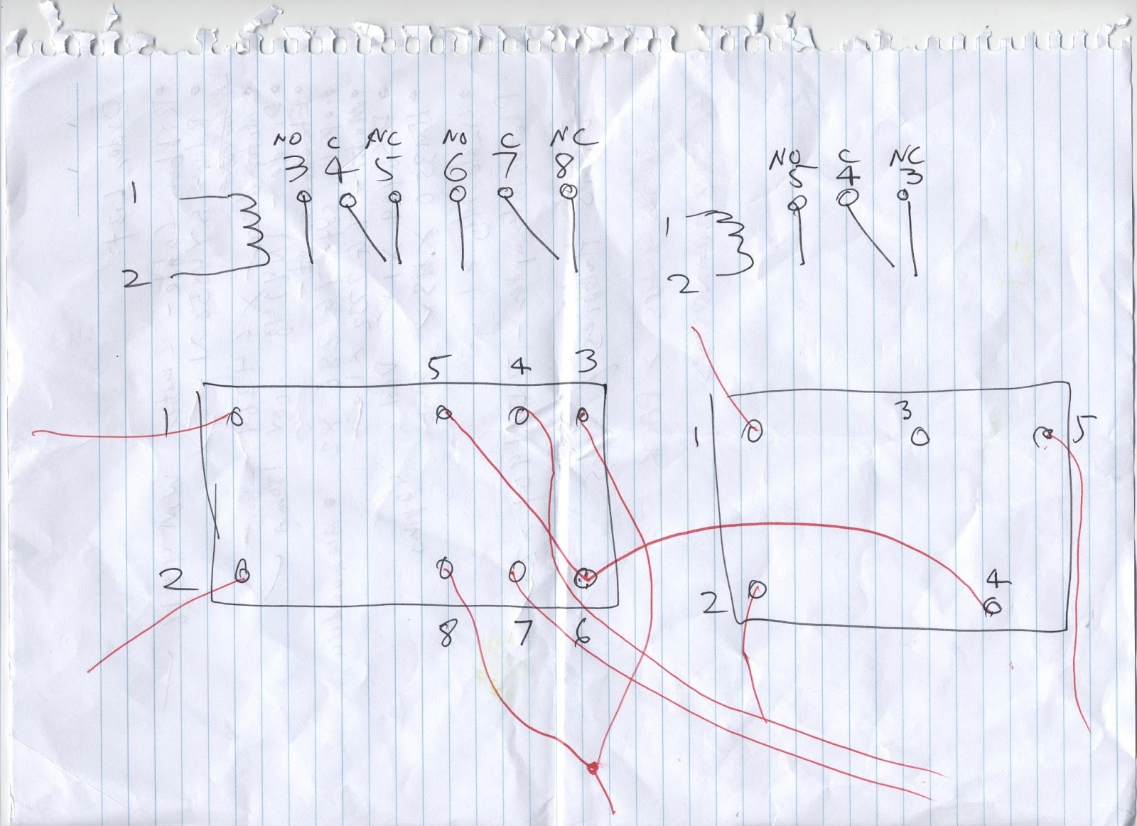
 Relay Wiring: Diagram of the DPDT and SPDT relays and how they have been wired (numbers correspond the "motor circuit diagram". This was repeated twice for the pairs of DPDT and SPDT relays. The single SPDT relay for the servo simply has all pins with single wires running out of them except for 3.

Motor circuit diagram (x2):

Buying parts

5/05/13
Today I went to stop down at jay car to pick up my parts. The general order is below:
  1. Rainbow cable (2 metres)-WM4516
  2. Relay (x3)-SY4050
  3. Relay (x2)-SY4052
  4. Motor (x2)-YG2732
  5. Diode (100V, 150mA) (x5)-1N4148
  6. Pulley Set Small (x2)-YG286
  7. A Cradle Relay (For electromagnet, not sure about part number just picked a random one off shelf)
  8. Photo interrupter (x1)-ZD1901
  9. Transistors (x5)-BC548
  10. 4K7 Resistors (x2 packs)-RR0588
  11. Terminals (x10)-HM3130
  12. 40 Pin Single row header strip-HM3212 
  13. TGY09S Turnigy Micro Servo (x1)(Not from Jaycar)
  14. A bunch of heat shrink tubes
  15. Arduino Uno (x1)(Not from Jaycar, too expensive)
  16. Experimenters board (200x80-dimensions in mm) (Not from Jaycar)