18/05/13
After on more day of soldering the circuit board is finally finished.
Below is the finished circuit. As you can see the final connections have been made from the relays. I also used some heat shrink and drilled some holes through the board to feed the wires under and make it nice and neat.

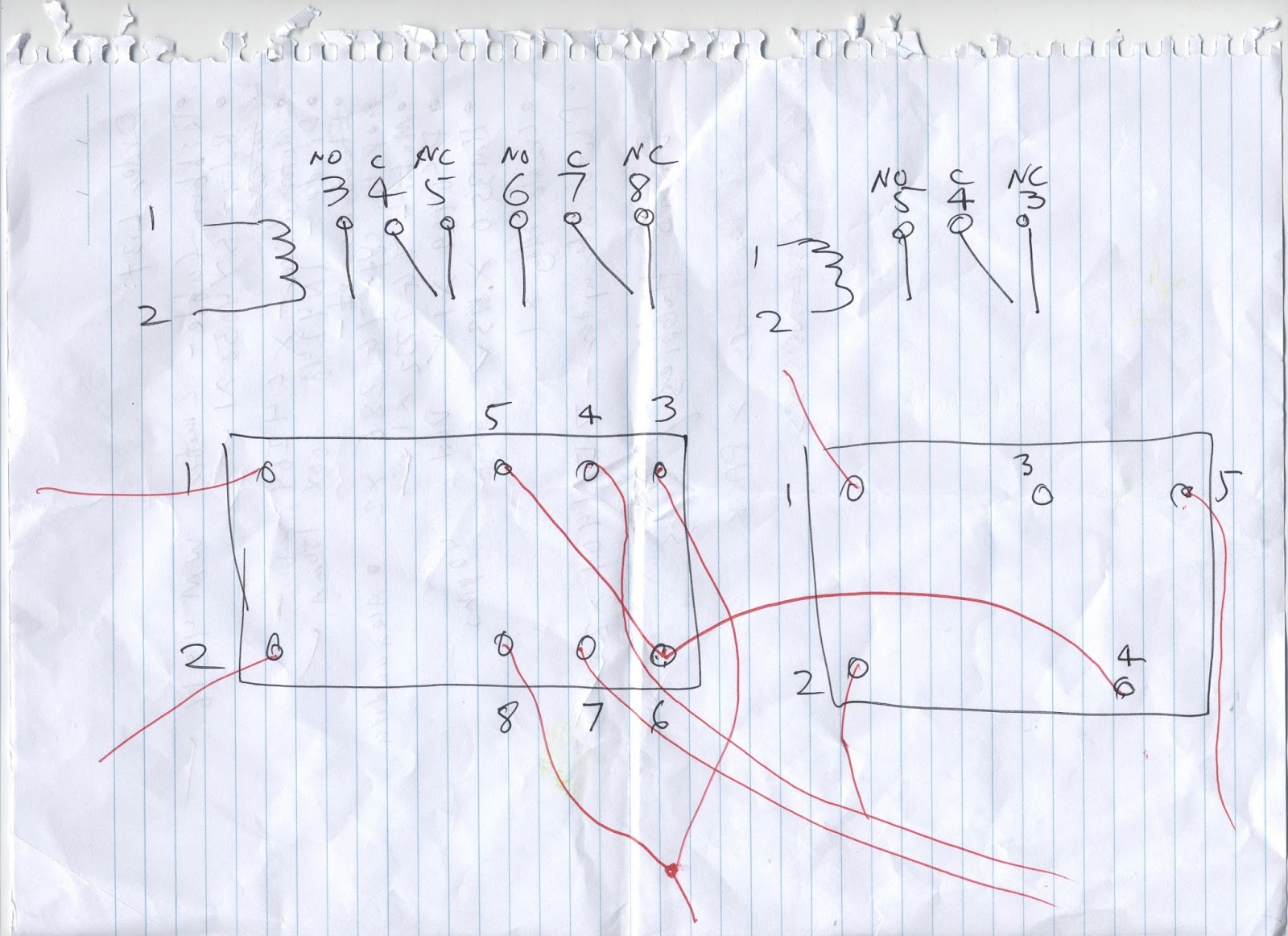
To be more specific, pins 4 and 7 of the DPDT have been fed through a hole that was drilled and connected to the two terminals on the left of the board. This will allow one motor to the switched. The same process has been repeated for the other DPDT except they have been attached to terminal 3 and 4. This will switch the second motor's direction. The 5th pin of the SPDT relay (furthest in picture) has been fed through another drilled hole and soldered to terminal 5. This will control the servo. The 6th terminal has been connected to the positive terminal (green curved wire). Next on both DPDTs pins 3 and 8 have been fed through a big hole drilled out and stuck together with heat shrink and connected to the positive terminal to supply power. Pin 5 on the two SPDTs (for the motors) and pin 4 for the servo SPDT have been connected to the negative terminal through another drilled hole. This will complete the motor circuit. The final connections made were from the motor/servo circuits, to the arduino microcontroller. By reference of an image of the uno, pins 2-6 were soldered to the resistors to join the arduino to the motors. Pin 7 was connected to what will be the white wire of the servo (or the left pin).The red pi of servo (centre) was connected to the 5V pin of the arduino and the black wire (right pin) was connected to the ground of the arduino. Finally, the other ground of the arduino was connected to the negative terminal. (to make reference to the relay pin numbers go to the picture below the bottom of circuit image.

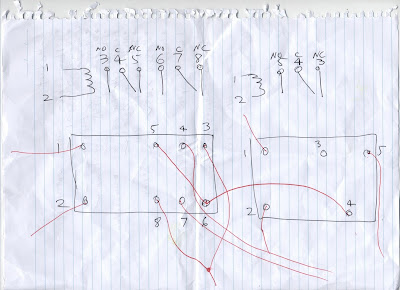
The final thing left to do was to check that the circuit functioned by connecting it to power but before risking smoking popping out of the relays, the circuit had to be checked. The rough circuit layout below was drawn for this purpose checking and ticking off correct connections. Only one mistake was found. The negative terminal was supposed to be connected to the ground of the arduino, but I interpreted the image wrong and soldered it to the wrong header pin. This was quickly fixed and after plugging the circuit into power it functioned as required =D
Next weekend I will be beginning the programming phase.


No comments:
Post a Comment