After two days of some intensive, soldering and wiring, the circuit board is near completion which means programming will begin soon.
In short, I have repeated the "Motor circuit" two times for each motor. I have then done it a third time but instead of using both a DPDT and SPDT relay, I have only used a SPDT which will be running the servo. The arduino uno is connected to the board using the 40 pin strips which have been snapped into pieces to match the arudino. Another small single 3 pin strip has been soldered in for the servo to plug into (position A20). In the circuit the relays have been taped together and then stuck to the experimenters board using double sided tape.
Top: Heat shrink was used to keep the wires already connected neat (so far thats only the 1s and 2s of the relays so its still a mess of wire)

Bottom: A hole was drilled on the top centre to allow the positive wires to feed from the relays to under the positive terminal block. The band side of the diodes have been bridged and also been connected to the positive terminal block to act as a block for back EMF.The transistors have had their centre base pin attached to the resistor. The emitters of the transistors has been bridged and joined to the negative terminal block. The pin connected to the arduino's ground has also been connected to the negative terminal. Each collector of the transistor has been connected to the 2nd pin of the relays (each fed through a hole which was drilled) and the other side of each diode.

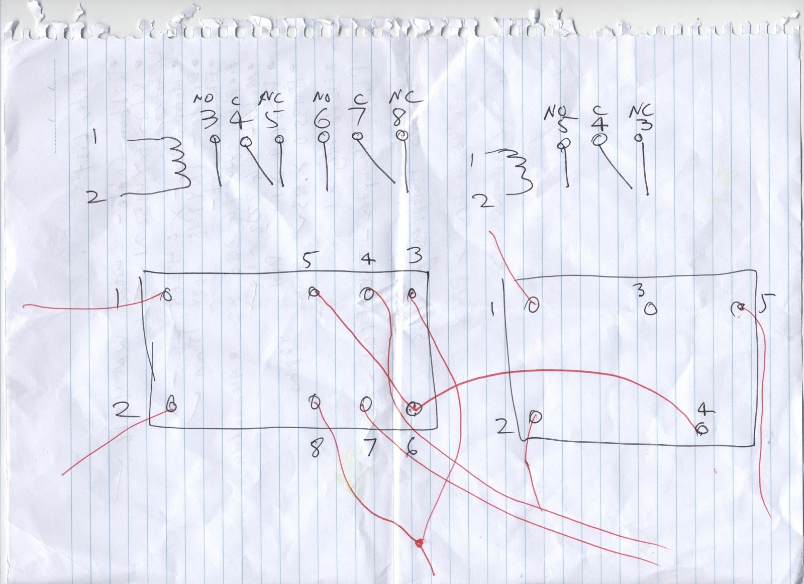
Motor circuit diagram (x2):

No comments:
Post a Comment